- 您现在的位置:买卖IC网 > Sheet目录1905 > ATMEGA644P-B15MZ (Atmel)IC MCU 8BIT 64KB FLASH 32VQFN
51
7674F–AVR–09/09
ATmega164P/324P/644P
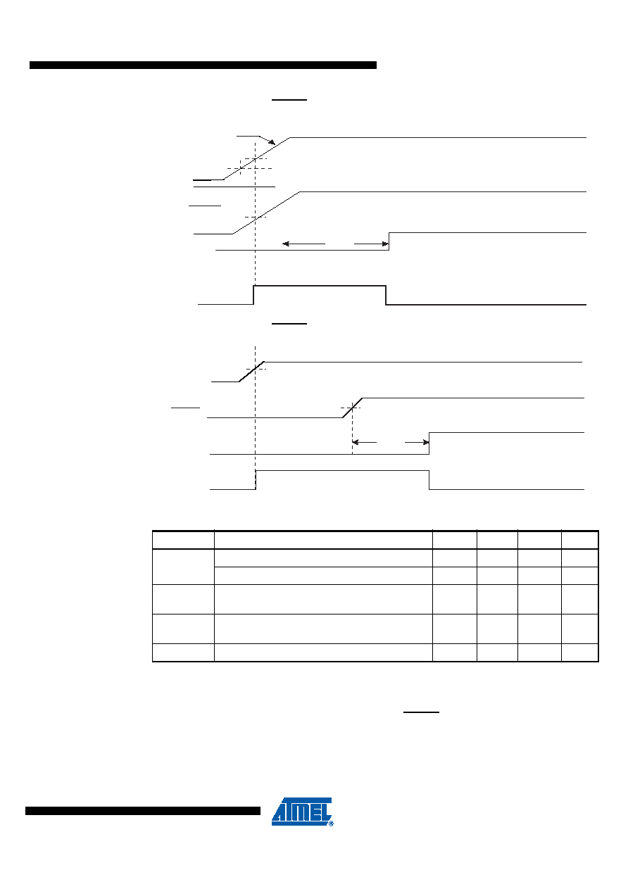
Figure 1. MCU Start-up, RESET Tied to VCC
Figure 2. MCU Start-up, RESET Extended Externally
Table 1. Power On Reset Specifications
Note:
1. Before rising, the supply has to be between
V
PORMIN and VPORMAX to ensure a Reset.
9.0.4
External Reset
An External Reset is generated by a low level on the RESET pin. Reset pulses longer than the
minimum pulse width (see “System and Reset Characteristics” on page 332) will generate a
reset, even if the clock is not running. Shorter pulses are not guaranteed to generate a reset.
When the applied signal reaches the Reset Threshold Voltage – V
RST – on its positive edge, the
delay counter starts the MCU after the Time-out period – t
TOUT – has expired.
Symbol
Parameter
Min
Typ
Max
Units
V
POT
Power-on Reset Threshold Voltage (rising)
1.1
1.4
1.7
V
Power-on Reset Threshold Voltage (falling)(1)
0.8
1.3
1.6
V
VPORMAX
VCC Max. start voltage to ensure internal
Power-on Reset signal
0.4
V
VPORMIN
VCC Min. start voltage to ensure internal
Power-on Reset signal
-0.1
V
VCCRR
VCC Rise Rate to ensure Power-on Reset
0.01
V/ms
RESET
TIME-OUT
INTERNAL
RESET
t
TOUT
V
RST
V
PORMA
X
VCC
CCRR
V
PORMIN
RESET
TIME-OUT
INTERNAL
RESET
tTOUT
VRST
VCC
发布紧急采购,3分钟左右您将得到回复。
相关PDF资料
ATMEGA644V-10PU
IC AVR MCU FLASH 64K 40DIP
ATMEGA645V-8MI
IC AVR MCU FLASH 64K 1.8V 64QFN
ATMEGA649-16MI
IC AVR MCU FLASH 64K 5V 64QFN
ATMEGA649V-8MI
IC AVR MCU FLASH 64K 1.8V 64QFN
ATMEGA8515L-8JUR
MCU AVR 8KB FLASH 8MHZ 44PLCC
ATMEGA8515L-8PJ
IC MCU AVR 8K 5V 8MHZ 40-DIP
ATMEGA8535-16JUR
MCU AVR 8K FLASH 16MHZ 44PLCC
ATMEGA8535L-8PJ
IC MCU AVR 8K 5V 8MHZ 40-DIP
相关代理商/技术参数
ATMEGA644PR212-AU
功能描述:8位微控制器 -MCU ATmega 644PV-10AU AT86RF212-ZU RoHS:否 制造商:Silicon Labs 核心:8051 处理器系列:C8051F39x 数据总线宽度:8 bit 最大时钟频率:50 MHz 程序存储器大小:16 KB 数据 RAM 大小:1 KB 片上 ADC:Yes 工作电源电压:1.8 V to 3.6 V 工作温度范围:- 40 C to + 105 C 封装 / 箱体:QFN-20 安装风格:SMD/SMT
ATMEGA644PR212-MU
功能描述:8位微控制器 -MCU ATmega 644PV-10MU AT86RF212-ZU RoHS:否 制造商:Silicon Labs 核心:8051 处理器系列:C8051F39x 数据总线宽度:8 bit 最大时钟频率:50 MHz 程序存储器大小:16 KB 数据 RAM 大小:1 KB 片上 ADC:Yes 工作电源电压:1.8 V to 3.6 V 工作温度范围:- 40 C to + 105 C 封装 / 箱体:QFN-20 安装风格:SMD/SMT
ATMEGA644PR231-AU
功能描述:8位微控制器 -MCU ATmega 644PV-10AU AT86RF231-ZU RoHS:否 制造商:Silicon Labs 核心:8051 处理器系列:C8051F39x 数据总线宽度:8 bit 最大时钟频率:50 MHz 程序存储器大小:16 KB 数据 RAM 大小:1 KB 片上 ADC:Yes 工作电源电压:1.8 V to 3.6 V 工作温度范围:- 40 C to + 105 C 封装 / 箱体:QFN-20 安装风格:SMD/SMT
ATMEGA644PR231-MU
功能描述:8位微控制器 -MCU ATmega 644PV-10MU AT86RF231-ZU RoHS:否 制造商:Silicon Labs 核心:8051 处理器系列:C8051F39x 数据总线宽度:8 bit 最大时钟频率:50 MHz 程序存储器大小:16 KB 数据 RAM 大小:1 KB 片上 ADC:Yes 工作电源电压:1.8 V to 3.6 V 工作温度范围:- 40 C to + 105 C 封装 / 箱体:QFN-20 安装风格:SMD/SMT
ATMEGA644PV-10AQ
功能描述:8位微控制器 -MCU AVR 64KB, 2KB EE 20MHz 4KB SRAM, 1.8V RoHS:否 制造商:Silicon Labs 核心:8051 处理器系列:C8051F39x 数据总线宽度:8 bit 最大时钟频率:50 MHz 程序存储器大小:16 KB 数据 RAM 大小:1 KB 片上 ADC:Yes 工作电源电压:1.8 V to 3.6 V 工作温度范围:- 40 C to + 105 C 封装 / 箱体:QFN-20 安装风格:SMD/SMT
ATMEGA644PV-10AQR
功能描述:8位微控制器 -MCU AVR 64KB FLSH 2KB EE 4KB SRAM-20MHz, 5V RoHS:否 制造商:Silicon Labs 核心:8051 处理器系列:C8051F39x 数据总线宽度:8 bit 最大时钟频率:50 MHz 程序存储器大小:16 KB 数据 RAM 大小:1 KB 片上 ADC:Yes 工作电源电压:1.8 V to 3.6 V 工作温度范围:- 40 C to + 105 C 封装 / 箱体:QFN-20 安装风格:SMD/SMT
ATMEGA644PV-10AU
功能描述:8位微控制器 -MCU AVR 64K FLASH 2K EE 4K SRAM ADC-10MHZ RoHS:否 制造商:Silicon Labs 核心:8051 处理器系列:C8051F39x 数据总线宽度:8 bit 最大时钟频率:50 MHz 程序存储器大小:16 KB 数据 RAM 大小:1 KB 片上 ADC:Yes 工作电源电压:1.8 V to 3.6 V 工作温度范围:- 40 C to + 105 C 封装 / 箱体:QFN-20 安装风格:SMD/SMT
ATMEGA644PV-10AUR
功能描述:8位微控制器 -MCU AVR 64KB FLSH 2KB EE 4KB SRAM-10MHz, 1.8V RoHS:否 制造商:Silicon Labs 核心:8051 处理器系列:C8051F39x 数据总线宽度:8 bit 最大时钟频率:50 MHz 程序存储器大小:16 KB 数据 RAM 大小:1 KB 片上 ADC:Yes 工作电源电压:1.8 V to 3.6 V 工作温度范围:- 40 C to + 105 C 封装 / 箱体:QFN-20 安装风格:SMD/SMT